JY02A BLDC Motor Driver IC Blocking Protection With Starting Torque Regulation Function
JY02A
Sensorless brushless DC motor control IC
JY02A is ASIC for sensorless brushless DC motor , with simple peripheral circuit, perfect function, compact size, simple debugging
(almost no debugging), high drive efficiency, flexible application, widely application, etc.
JY02A is a pure hardware application IC, which solve the trouble of writing programs. JY02A internally solidifies various sensorless
brushless DC motor drive control circuits, such as adaptive start circuit, power compensation circuit, Q value correction circuit, power
factor correction, Phase detection circuit, bidirectional operation decoding circuit, locked-rotor protection circuit, back electromotive
force detection circuit, current detection & control circuit, voltage detection & protection circuit, etc., after a very few amount of external
component adjustment, can drive various sensorless brushless DC motor, JY02A has a certain load-starting capability, which is very
important in most applications. JY02A can be applied to three-phase DC brushless motor with "Y" and "triangle" connection.
Applications: sweeping robots, automotive water pumps, wall-hung boiler circulation pumps, home booster pumps, oxygen generators,
various fans/blowers, electric screwdrivers, electric curtains, automatic doors, hydraulic oil pumps, high pressure air pumps, automotive
air conditioning compressors , DC brushless compressor, AGV trolley, various linear and loop logistics sorting equipment, lawn mower,
sprayer, underwater propeller, etc.
Functional characteristics:
☆Working voltage: 4.5 v-5.5 V. ☆Working temperature: -55-125 ℃
☆Drive mode: SPWM ☆Adaptive motor: Sensorless BLDC motor
☆Direction control: CW/CCW ☆Soft reversing: Yes
☆Speed signal: Yes ☆Overload protection: Yes
☆Current closed loop: Yes ☆Constant current drive: Yes
☆Blocking protection: Yes ☆Starting torque regulation: Yes
☆Soft starting: Yes ☆Special technology: JYKJ full condition safety start function
☆Speed adjustment: linear ☆EAI self-adaptation function
PIN NAME FUNCTION REMARK
DC Electrical Characteristics
JY02A internal functional block diagram
Note: JY02A drive signal is positive polarity output, choosing adapted MOS drive circuit and power MOS is very important!
JY02A Drive mode and parameters:
1:UH/VH/WH phase top drive PWM output,UL/VL/WL phase bottom drive commutation signal output, this drive mode
is a economic way to reduce the costs of hardware, especially in application of high voltage and high-power motor
drivers. top drive PWM output mode is more easier circuit and higher stability than bottom drive PWM output mode.
2:The PWM frequency of JY02A is 13KHz, which not only takes into account the comprehensive ratio of efficiency
and noise, but also increases the power and reduces the power consumption of the driving circuit . The torque of the
motor is higher than that of 20KHz under the same power supply.
Pulse of JY02A
Please take a note that JY02A output one pulse signal during the BLDC motor commutating phase each time. It means
JY02A not produce one pulse when the motor turn a round. For example as following schematic diagram: its an inner
rotor, 2 pairs pole motor, it means the motor needs commutating phase for 6 times for each round, so JY02A will
output 6 pulses each motor round
Schematic diagram of internal structure of 2 pair pole inner rotor motor
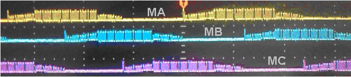
Forward drive output oscillogram
(SPWM output close to sinusoid, well electromagnetic noise restraint )
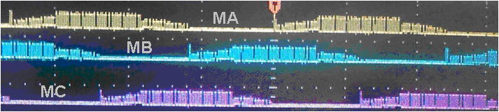
Reversing drive output oscillogram
(SPWM output close to sinusoid, well electromagnetic noise restraint )
Schematic of application:
1. JY02A typical application Schematic for sensorless brushless DC motor
JY02A has built-in BEMF detection circuit
JY02A no need external Comparator Circuit for sensorless brushless DC motor
Remark:
Is is the current signal feedback input terminal. When the Is terminal voltage reaches to 40mV, the system starts overload monitoring
and enters the constant current control state. The driving current is no longer increased by the VR terminal voltage or the load increases.
This function effectively prevents MOSFET burn out when the load is too large, and can continue to provide power to the motor to maintain
the maximum driving state. When the accidental current continues to increase, the voltage of the Is terminal reaches or exceeds 90mV,
the JY02A will immediately enter to protection state, and close all outputs ,the protection only released when VR is reduced to 0V
or re-powered
According to Ohm's law, we only need to change the value of R to change the protection current value. JY02A is very flexible in
current protection (more on this later)
Functional description and application considerations
a) Overload protection and current sampling resistance value selection:
JY02A has a relatively complete overload protection function. the overload protection and current abnormal protection function of JY02A
will take effect only under the condition of the current sampling resistor R is selected properly. When the Is pin voltage reaches 0.40mV,
the overload monitoring starts and enter into constant current state and keeps the driving current constant. At this state, the driving
current no longer rises with the voltage of the VR pin, and will not increase with the increase of the load. In this state, JY02A will continue
to provide a constant power for the motor and keeps the motor in normal working state. If the Is pin voltage reaches or exceeds 90mV,
the system will judge all the outputs within 4.5 microseconds.
Here is a detailed example how to select properly R value as follow:
R value formula: I = 0.04/R
I: Constant current setting value, unit: A
0.04: is the voltage value of Is pin of JY02A
R: current limiting resistance, unit: Ohm
For example, a controller with an operating current of 3A , set the constant current to 5A for safety, and the system keep the current at
5A when the current reaches or exceeds 5A, after the formula I = 0.04 /R, R=0.04/I so R value = 0.04 / 5=0.008 Ohm, so the current
sampling resistor should use a power resistor of 8 milliohms (current sampling resistor normally is cement resistor and constantan wire)
b) locked-rotor protection:
JY02A has automatic restart function. Once the running motor is blocked by external force, the system will automatically protect and
restart. If the restart is unsuccessful for 10 times, it will automatically stop output. Disconnect the power or reduce the voltage of the
VR pin to 0V to unlock the protection. Increase the VR voltage to restart the motor.
c) Z/F soft reversing:
The 16th pin Z/F of JY02A is the reversing control pin. This pin can be connected to 5V or GND. JY02A has soft reversing function.
This function protects the MOSFET and motor in many applications, and improves the reliability and service life, the specific operation
is that when the motor is rotating in one direction, when the Z/F voltage level changes, the driver stops output first, the motor rotates
freely till stop, and then starts to run in the other direction.
d) FG speed signal feedback:
JY02A also outputs the speed pulse signal while driving the motor. JY02A will output one pulse every phase commutating. This is perfectly
reflected in high-end applications. In the case of precise speed control, such as DC brushless fan, DC Brushless pumps, etc.,
With the speed signal feedback, these functions are easy to achieve, Such as require stable speed and stable torque, and closed-loop
control solution.
e) TC Temperature protection port:
JY02A has an external connect temperature protection function. The application is quite simple, only an external NTC and a resistor are
required, can place the NTC in the place where need be monitored, such as MOSFET or motor. When the temperature reaches a certain
value, the system will automatically protect, the system will restart after the temperature down to safety value. it is recommended
parameters of NTC: NTC of 10K3950K, divider resistor with 10K 1%, according to this parameter, the temperature will automatically
protect when the temperature reaches 100 degrees, of course, you can also replace other models NTC or adjust divider resistor
according to the actual application. The value of the resistor reaches the temperature value that you want to protect.
f) QD Starting torque adjustment:
By adjusting the voltage of the QD terminal, the starting torque can be directly changed. The voltage adjustment range is 0V-2.5V, and the
normal motor starting torque voltage is between 0V - 0.8V (the starting torque is not as bigger as better)
Summary:
There are many factors affecting the DC brushless Hallless motor driver, such as the working voltage, speed, commutation angle, load,
inductance, back EMF, starting load, etc., which will affect the DC brushless motor drive performance. The driving effect of the motor,
so more testing are required to make a perfect high-efficiency, stable DC brushless sensorless motor driver .
Declaration:
In order to improve the performance of DC brushless sensorless motor driver, reduce the volume, reduce the production and development
costs, JY02A is our the second DC brushless sensroless motor driver IC that does not require an external comparator. JY02A integrates
all the circuits of DC brushless sensorless motor driver (excluding power components). In order to better service to our customers, we
offer three JY02 typical application circuits for reference. We will continue to improve its performance according to market applications.,
actual IC function may be slightly different from the introduction of this article, if you have any problems in the application, you can
contact us for the latest information.
Here are three typical application schematics and product photos for reference. These schematics are all validated for mass production
and related physical products provide learning research. These three typical application schematics basically cover the most of applications.
JY02A small power DC brushless Hallless motor drive application schematic
Working voltage:7.5V----28V
Max working current:3A
Max power output:30W
Small power dc brushless sensorless motor driver product photo
Size:L 45mm *W:32mm*H 12mm
JY02A middle-size power DC brushless Hallless motor drive application schematic
Working voltage:12V----36V
Max working current:16A
Max power output:500W(MOS:TO220)
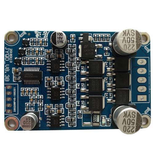
Middle-size power dc brushless sensorless motor driver product photo
Size:L 63mm *W:42.5mm*H 12mm
JY02A High voltage DC brushless Hallless motor drive application schematic
Working voltage:80V----265VAC
Max working current:1A
Max power output:150W
High voltage DC brushless sensorless motor driver product photo
Size:L 77mm *W:60mm*H 32mm
DOWNLOAD JY02A USER MANUAL
 JY02A_V2-English2.pdf
Product Tags:

|
|
JY02A BLDC Motor Driver IC Blocking Protection With Simple Peripheral Circuit Motor Controller IC Images
|